• TalkBass has been independent since 1998. Add your voice.
    Create a free account to reply to discussions, view embedded media, and browse with fewer display ads.
    Join freeLog in
    Want zero display ads or expanded classifieds tools? Compare plans.

Fæpbœx III: 3-Band Preamp

Apr 5, 2011
1,287
630
CO
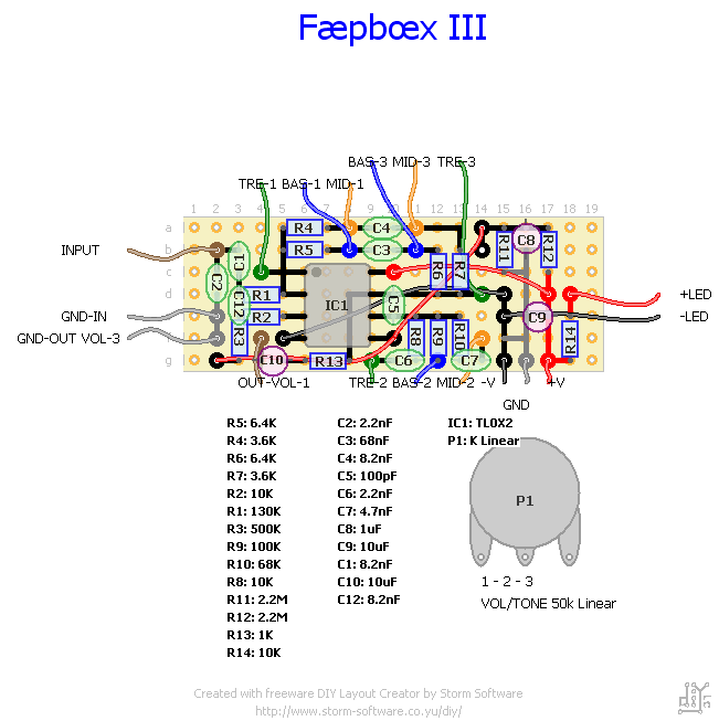
Made a rip-off of somebody else's ripoff of a Stingray 3-band preamp. Didn't like the guy's layout, so I made mine with a clockwise rotation on the signal flow. Yes, you may notice that the digital layout is slightly smaller than the one in the picture -- I didn't realise how large those components were in real life. Just started from the input and stretched it out just a smidge.

Works great, thanks to some help. I had added a fourth capacitor instead of a straight shot between -V and ground. Don't do that. Fixed on schematic.

Next build of it will be on a smaller board and be placed inside of a 1590 enclosure.
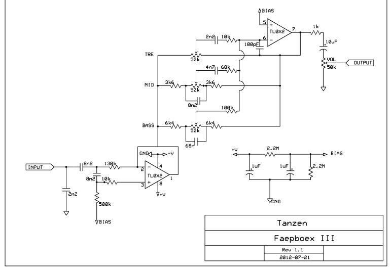
FBIIISchem.jpg

FaepboexIIIRender.gif

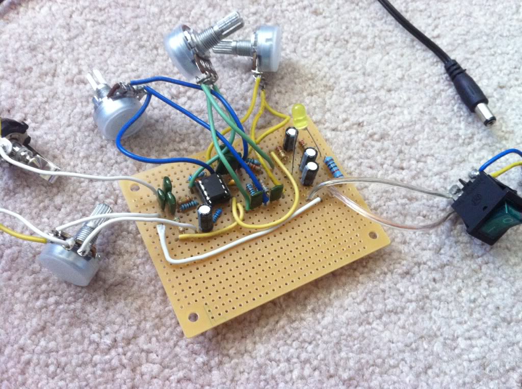
IMG_5267-1.jpg

(Heh, picture from before I scrapped that fourth capacitor. Bias power is yellow wire, ground is white; +/-V is wired from one side to the other on the underside.)
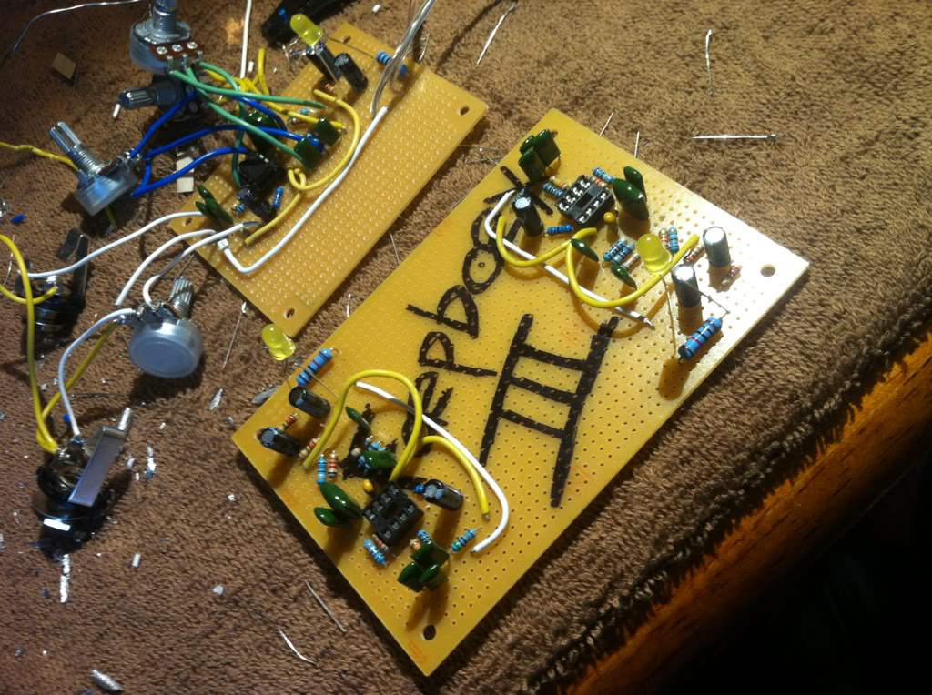
FBIII.jpg

Built two on the same board, to be split and put into the final Bœxes, one sent to a friend. How romantic.

 
Suggestions on layout? Feel free. Not asking for a lot beyond an eye to notice something that I didn't.

About ready to build these things, finally. Figured I'd be a perfectionist and draft up some lines for when I take it to the drill press. To be printed and used for drill press guides on a 1590 enclosure. Most of the lines are merely for reference.

God forbid somebody accuse me of not putting in enough LEDs.

Why yes, I am drafting this up using Adobe Illustrator, everything being done according to a grid and using centimeters for precision. Measured up all the components by hand, beforehand.

1590FBIIIV1.png

1590FBIIIV1Color.png

Worked just fine for my guitar that I built a few years back.
SquarePegsIIIF.jpg
 
Looks fun. Your input stage is quite confusing???!!!

Where do you come up with the design? It looks like a lot of components for a basic buffer? Is this going to be used with an active or passive bass?

OH I see! Its the Sting Ray schematic. Sorry. I wasn't paying attention.

As it stands, it looks like it would sound the best with a passive instrument without any buffers (tamer highs). I'd love to hear sound samples.
 
father of fires said:
Looks fun. Your input stage is quite confusing???!!!

Where do you come up with the design? It looks like a lot of components for a basic buffer? Is this going to be used with an active or passive bass?

OH I see! Its the Sting Ray schematic. Sorry. I wasn't paying attention.

As it stands, it looks like it would sound the best with a passive instrument without any buffers (tamer highs). I'd love to hear sound samples.

You can find sound samples under the "somebody else's ripoff" link on the original post.

I'm building it in an enclosure because I have four instruments and they're all passive. :)
 
EricssonB Hello, I need help !!! please ... I built twice the preamplifier and does not work, it seems to have no gain. You feed it with a 9V battery or two? I'm testing the pre with a Yamaha RBX375 bass. Thanks for your help!!!
 
EricssonB Hello, I need help !!! please ... I built twice the preamplifier and does not work, it seems to have no gain. You feed it with a 9V battery or two? I'm testing the pre with a Yamaha RBX375 bass. Thanks for your help!!!

When I turn on the preamplifier, background noise is heard as if working. I turn pots and note that it works the tone control and volume, but seems to have no input signal. I tried with passive mics bass and also I have connected a cell, but does not work.

Sorry to hear you're having problems with it. (I can't believe it was four years ago I built this thing; time flies.)
-- I actually made it in pedal form and generally run it with a 12v adapter. The IC is rated for 15v (if I remember correctly) so two 9v batteries might fry it. Just use one.
-- I think I may have had a similar problem and it had to do with the input-side of the IC not getting power (the RED connection between G2 and A14). Definitely double check how the power is going through it. That's where I'd start.

Do you have extra ICs? I know I ruined a good few of them trying to get this to work. Maybe replace those if you haven't already.
 

Latest posts